



Inspection Equipment
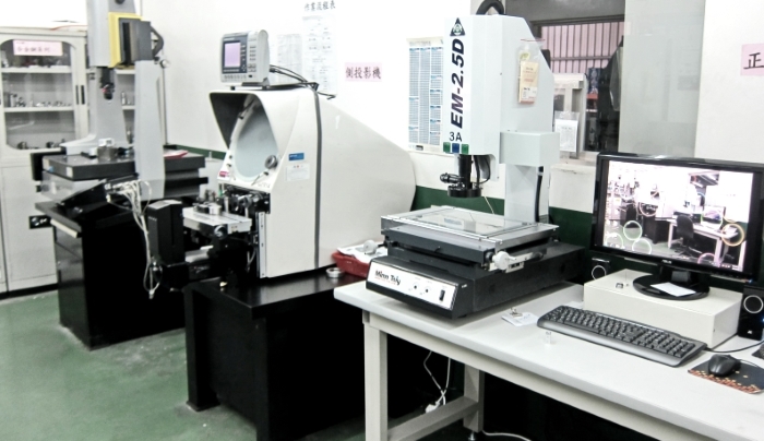
APPORO inspects parts in-house at our Taiwan facility with 13 inspection and measuring instruments in five categories: coordinate measuring machines (CMM), image and vision measuring systems, a profile projector, height and hardness testers, and surface roughness testers. The full list, with brand, model and key specification, is below.
The coordinate measuring machines are used where a drawing carries many dimensions, or features that are hard to reach any other way; simpler dimensions are checked on gauges, height gauges or the vision systems. A long measuring program can occupy a machine for some time, so having three means one job does not hold up first article or incoming inspection on another. Results are recorded against the dimensions on your drawing and can be supplied on request.
Inspection Equipment List
| Category | Equipment | Brand / Model | Qty | Key specification |
|---|---|---|---|---|
| Coordinate measurement | Coordinate Measuring Machine (DCC) | Sheffield Discovery 8 III | 1 | 508 × 609 × 406 mm · volumetric accuracy 0.010 mm |
| Coordinate Measuring Machine (DCC) | Brown & Sharpe Gage 2000 | 1 | 458 × 510 × 406 mm · E = 4.0 + L/200 µm | |
| Coordinate Measuring Machine (DCC) | Brown & Sharpe MicroXcel PFx 454 | 1 | 400 × 500 × 400 mm | |
| Image & vision | Image Dimension Measurement System | KEYENCE IM-8020 | 1 | ±2 µm · 0.1 µm display unit · rotary unit fitted |
| 2.5D Vision Measuring Machine (CNC) | Mimn Taiy CNC-2.5D 3020 | 1 | 300 × 200 × 150 mm · ±(3 + L/200) µm | |
| 2.5D Vision Measuring Machine | Mimn Taiy EM-2.5D 3A | 1 | 300 × 200 × 150 mm · 0.5 µm resolution | |
| Optical | Profile Projector | Baty R14 | 1 | 175 × 100 mm · Ø340 mm screen · 0.5 µm |
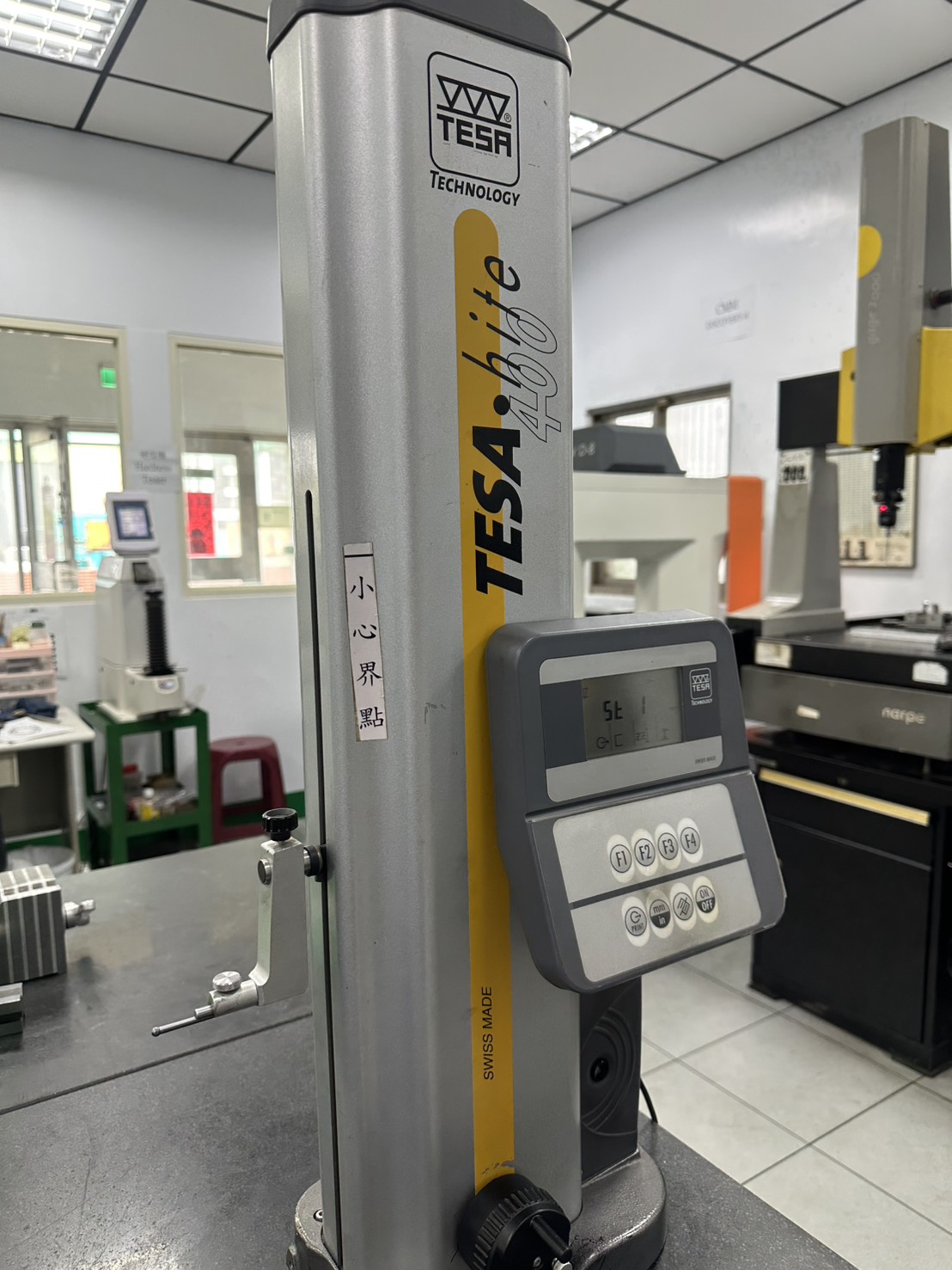
| Height | Digital Height Gauge | TESA-HITE 400 | 2 | 0–400 mm · resolution to 0.0001 mm |
| Digital Height Gauge | Trimos Mestra 600 | 1 | 610 mm · MPE 1.4 + L/400 µm | |
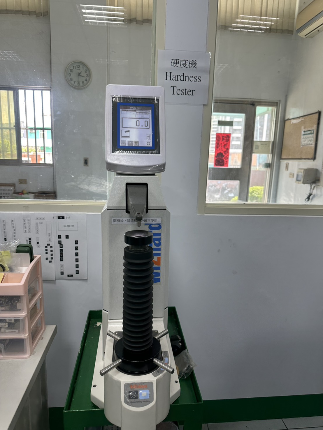
| Hardness | Digital Rockwell Hardness Tester | Mitutoyo Wizhard HR-521 | 1 | Rockwell · Rockwell Superficial · Brinell |
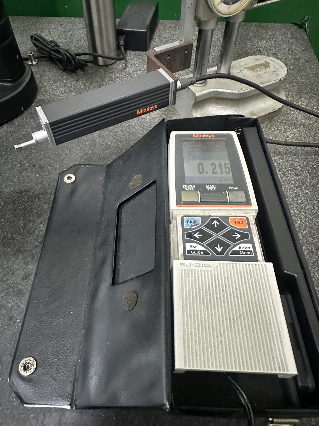
| Roughness | Surface Roughness Tester | Mitutoyo Surftest SJ-210 | 2 | Ra / Rz / Rq · 360 µm range |
| Gauges | Pin gauges · thread plug and ring gauges · setting ring gauges · micrometers · bore gauges | See below | ||
Measurement Capability
Metrology uses the 10:1 rule: measuring equipment should be about ten times more accurate than the tolerance it checks.
Our highest-resolution instrument, the KEYENCE IM-8020, measures to ±2 µm (±0.002 mm) in high-precision mode, with a display unit of 0.1 µm. By the 10:1 rule, that supports verifying tolerances down to about ±0.02 mm, which covers most precision turned and milled parts.
Controlled measuring environment
Dimensional inspection is carried out in a metrology room held at 23 ±2 °C and 45–55 % RH, monitored continuously. Steel changes length by about 12 µm per metre for every 1 °C, so on close-tolerance work the room matters as much as the instrument.
How each tolerance band is verified
| Tolerance band | Primary method | Equipment used |
|---|---|---|
| ISO 2768-m / -f general tolerances | Height gauge, pin and thread gauges, optical comparison | TESA-HITE 400, Baty R14, gauge sets |
| ±0.05 to ±0.10 mm | 2.5D vision or coordinate measurement | Mimn Taiy 2.5D, Brown & Sharpe CMM |
| ±0.02 to ±0.05 mm | Coordinate or image measurement | Sheffield Discovery 8 III, KEYENCE IM-8020 |
| ±0.01 to ±0.02 mm | Image measurement, high-precision mode | KEYENCE IM-8020 |
| Tighter than ±0.01 mm | Comparison against a calibrated master at nominal size | Gauge blocks, setting rings Ø10–50 mm, comparators and gauge stands |
Close-tolerance and ground work
We accept tolerances tighter than ±0.01 mm. Outside diameters have been supplied at ±0.005 mm, and at unilateral bands such as +0.007 / −0 mm, with the diameter ground to final size.
Close-tolerance diameters are measured by comparison rather than read off an absolute scale. The instrument is zeroed on a master close to the nominal size, and the part is read as a departure from it. Because the instrument only works across a few microns of travel, most of its own scale error stays out of the result. Bores are read with bore gauges zeroed on a calibrated master: setting rings, of which we hold a set across Ø10–50 mm, or gauge blocks for sizes above that. Outside diameters are read with a micrometer zeroed on gauge blocks, or on the micrometer’s own calibration standard, at the nominal size.
For general tolerance classes, see our General Tolerances ISO 2768 / JIS B 0405, B 0419 chart. For hole and shaft fits, see Tolerances for Holes and Shafts. For surface finish grades, see the Surface Roughness Table.
If a dimension has to be verified in a particular way — a specific instrument, a datum scheme, or your own inspection procedure — tell us before the job is quoted. Send the drawing with your RFQ and mark anything that has to be inspected a particular way.
Coordinate Measuring Machines (CMM)
A coordinate measuring machine (CMM) records points on the part with a touch probe in three axes, then compares the geometry directly against the drawing. This includes profile, true position and form tolerances that hand tools cannot check.
All three CMMs are DCC machines running programmed measurement routines. Once a routine is proven on the first article, every later piece is measured through the same sequence, so the result does not depend on the operator.
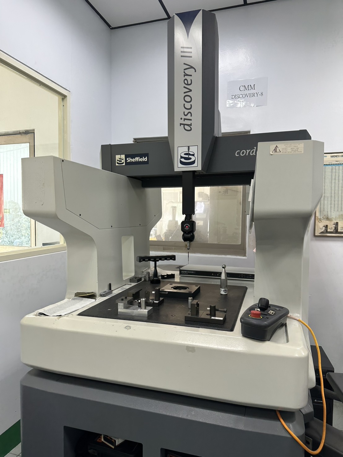
Sheffield Discovery 8 III
- Measuring range: 508 × 609 × 406 mm (20″ × 24″ × 16″)
- Volumetric accuracy: 0.010 mm
- Linear accuracy: X 0.004 mm · Y 0.0045 mm · Z 0.0035 mm
- Repeatability: 0.0025 mm
- Renishaw PH6 auto-indexing probe head
- DCC operation for repeatable 100% inspection across a production run
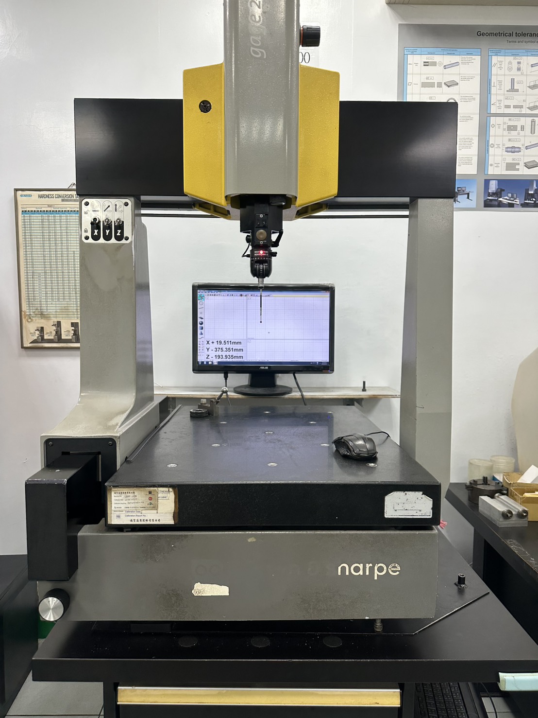
Brown & Sharpe Gage 2000
Touch-probe CMM used to check the geometry of custom machined parts, including complex profiles that conventional tools cannot inspect.
- Measuring range: 458 × 510 × 406 mm (18″ × 20″ × 16″)
- Accuracy to ISO 10360-2: E = 4.0 + L/200 µm · R = 6.2 µm
- Repeatability: 4.0 µm
- Resolution: 0.0001 mm
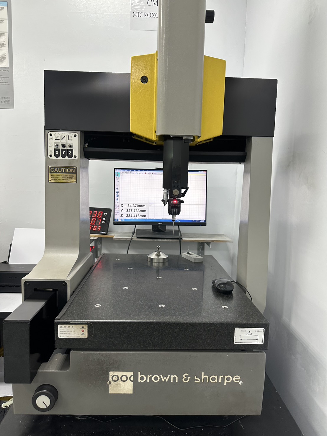
Brown & Sharpe MicroXcel PFx 454
The third CMM in the inspection room. It handles first article work and in-process checks while the other two run production inspection routines.
- Measuring range: 400 × 500 × 400 mm
- Renishaw probe head, DCC operation
Accuracy figures above are the equipment manufacturers' published specifications. Calibration certificates for the machines used on your parts are available on request.
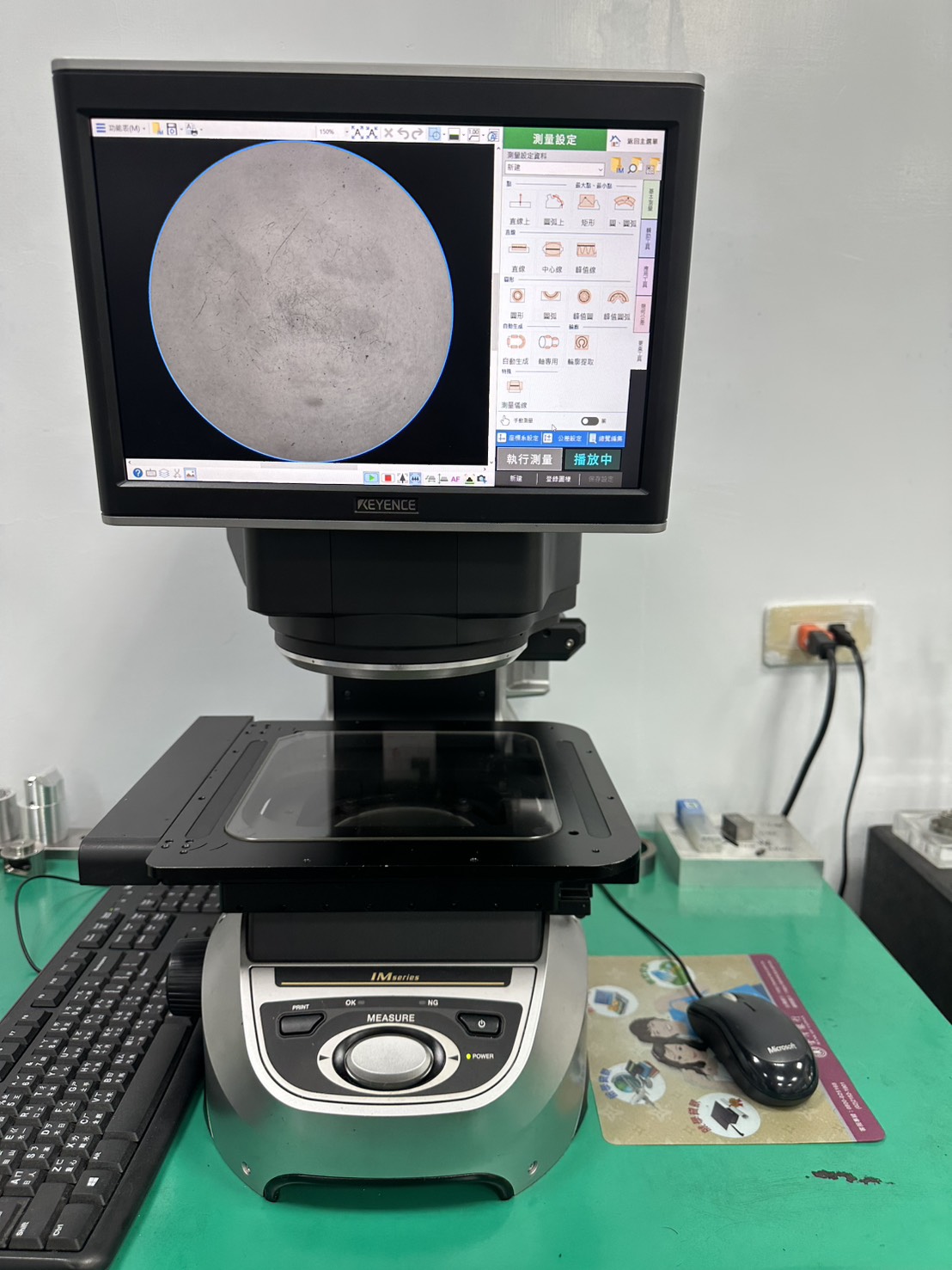
KEYENCE IM-8020 Image Dimension Measurement System
The IM-8020 captures an entire part in one image and measures many dimensions at once against a registered drawing. A profile projector needs an operator to align and read each feature by hand; the IM-8020 returns a complete dimensional result from one placement on the stage, with no operator-to-operator variation.
Rotary unit for multi-face measurement
A rotary unit turns the part under the lens through a full revolution. Features around the circumference, and on faces that would otherwise need the part to be re-fixtured, are captured in a single setup. On turned parts, this removes the repositioning error that builds up when a component is measured face by face.
Specification
| Field of view, wide-field mode | 200 × 200 mm |
|---|---|
| Field of view, high-precision mode | 125 × 125 mm |
| XY stage travel | 100 × 100 mm, motorised |
| Z travel | 75 mm, motorised |
| Minimum display unit | 0.1 µm |
| Accuracy, high-precision mode | ±2 µm |
| Repeatability, high-precision mode | ±0.5 µm |
| Accuracy, wide-field mode | ±3.9 µm |
| Image sensor | 1″ 20-megapixel monochrome CMOS |
| Optics | Double telecentric lens |
| Maximum stage load | 5 kg |
2.5D Vision Measuring Machines
Vision measuring machines measure without touching the part. This suits thin sections, soft materials, polished surfaces and small features, where the contact force of a touch probe would deflect or mark the workpiece.
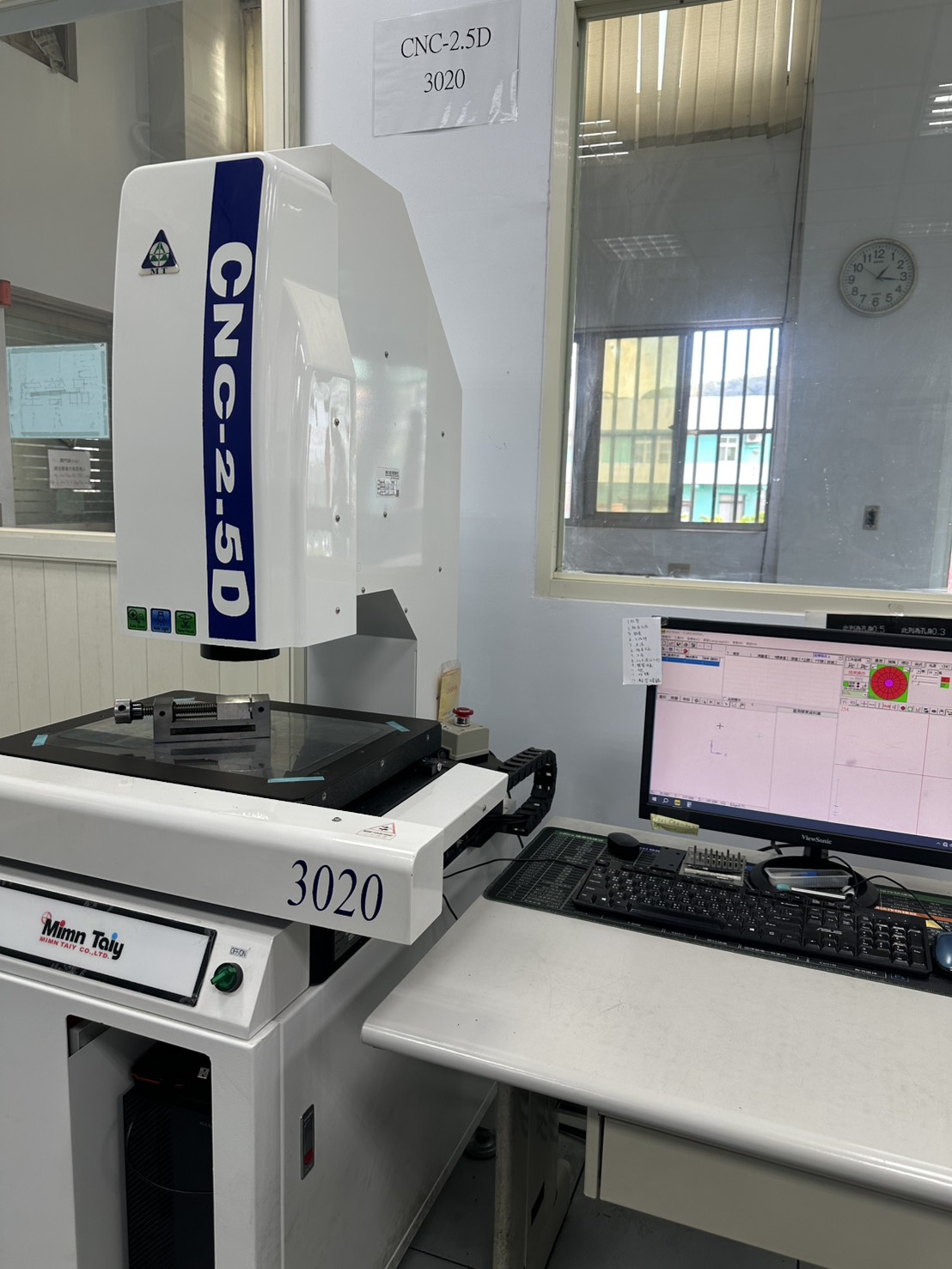
Mimn Taiy CNC-2.5D 3020
Programmed non-contact measurement with servo-driven X, Y and Z axes. Once a routine is written for a part, every later piece is measured through the same sequence, so repeat inspection does not depend on operator judgement.
- Measuring travel: 300 × 200 × 150 mm
- Accuracy: ±(3 + L/200) µm at 20 ±1 °C
- Scale resolution: 0.001 mm
- Optical magnification 0.7–4.5×, auto zoom, auto focus
- Programmable LED contour and surface illumination; precision granite stage
Mimn Taiy EM-2.5D 3A
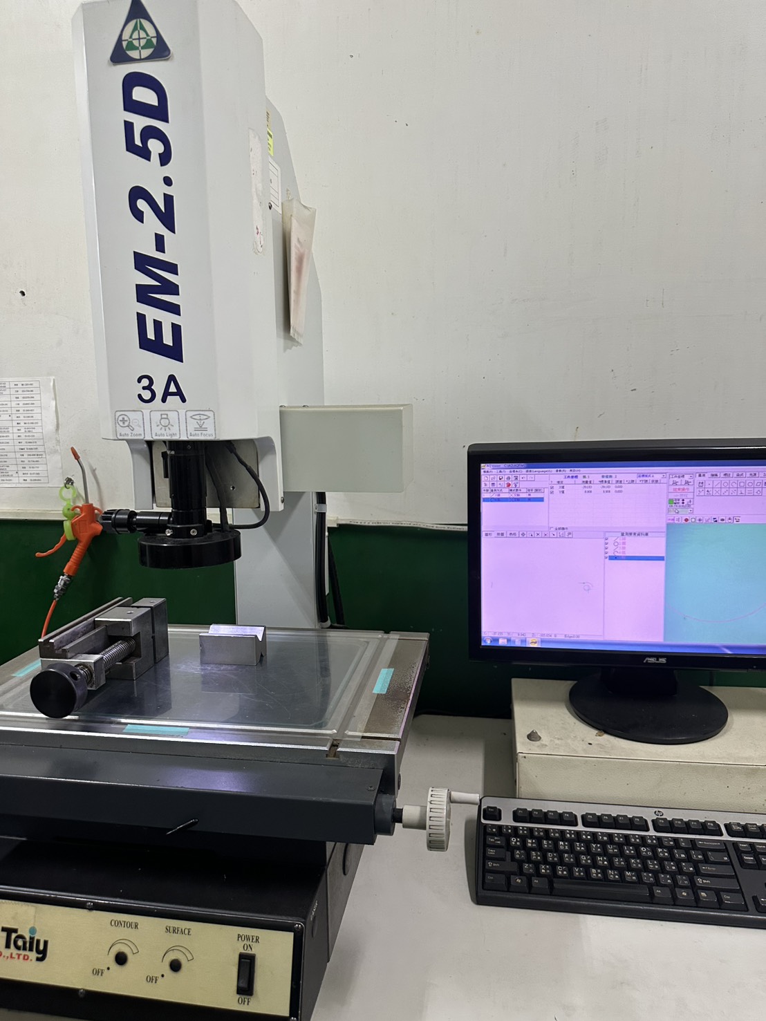
Semi-automatic vision machine with a servo-driven Z axis and auto focus. It handles profile and hole-position work alongside the CNC unit, so non-contact inspection does not depend on a single machine.
- Measuring travel: 300 × 200 × 150 mm
- Scale resolution: 0.0005 mm (0.5 µm)
- Accuracy: ±(3 + L/200) µm at 20 ±1 °C
- Optical magnification 0.7–4.5×, auto zoom, auto focus
- Programmable LED contour and surface illumination; precision granite stage
Baty R14 Profile Projector
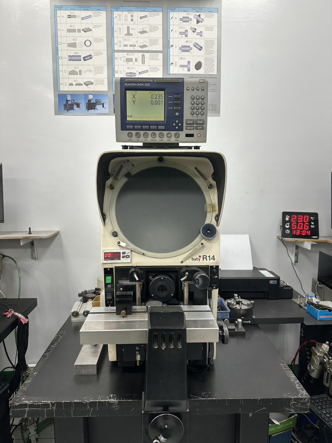
A bench-mounted horizontal profile projector. It projects the part's silhouette onto a 340 mm screen and compares it with an overlay chart, which makes it the fastest way to check thread forms, radii and chamfers. These features are slow to probe on a CMM but easy to read optically.
- Measuring range: 175 × 100 mm workstage
- Screen: Ø340 mm (14″) with 90° crosslines and chart clips
- Resolution: 0.5 µm; angular measurement to 1 minute of arc
- Magnifications: 10×, 20×, 25×, 50× and 100×
- Helix adjustment of the light source ±7°, for projecting true thread form
- Profile illumination by halogen lamp with green filter; fibre-optic surface illumination
- Quadra-Chek 200 digital readout
Thread forms are compared against the profiles in our Metric Thread Chart.
Height, Hardness and Surface Roughness Testing
Digital Height Gauges
Used for heights, step differences, hole pitch and parallelism, and as the routine in-process check at the machine.
- TESA-HITE 400 (×2) — 0–400 mm range; resolution to 0.0001 mm; maximum permissible error (2.5 + 4L/1000) µm; repeatability ≤2 µm on flat surfaces, ≤3 µm in bores
- Trimos Mestra 600 (×1) — 610 mm range; resolution 0.0001 mm; maximum permissible error 1.4 + L/400 µm; repeatability 0.5 µm
Mitutoyo Wizhard HR-521 — Digital Rockwell Hardness Tester
Hardness is verified after heat treatment and on incoming material where the specification calls for it.
- Scales: Rockwell, Rockwell Superficial and Brinell
- Maximum specimen height: 205 mm
- Throat depth: 150 mm
For conversion between scales, see our Hardness Conversion Chart.
Mitutoyo Surftest SJ-210 — Surface Roughness Tester
Two units, used to verify Ra, Rz and Rq against the finish called for on the drawing, whether as-machined or after plating.
- Z measuring range: 360 µm
- Parameters: Ra, Rz, Rq and others
For the relationship between roughness grades and machining processes, see our Surface Roughness Table.
Gauges and Hand Measuring Equipment
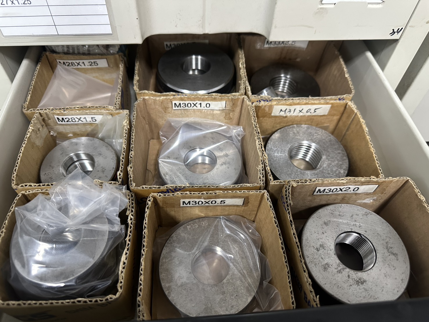
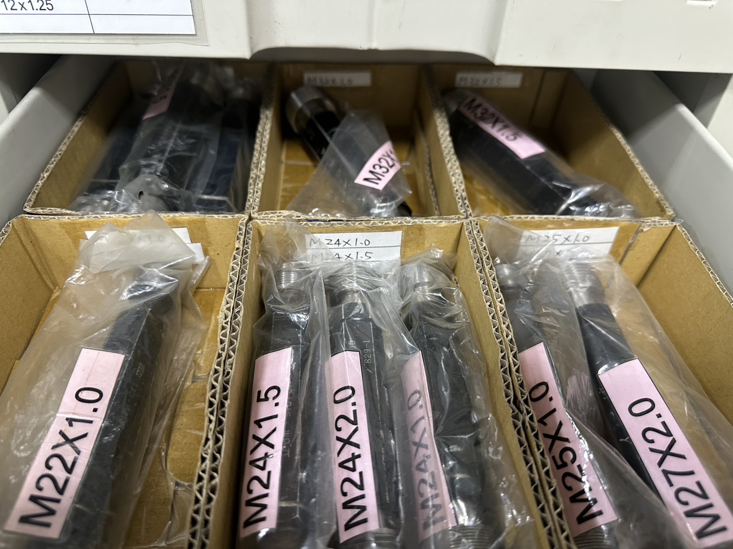
Not every feature needs a machine. Attribute checks, such as whether the thread accepts the gauge or the pin enters the hole, give a pass or fail with no reading to record and no operator interpretation. That makes them the fastest and most reliable check on high-count production.
Gauges are held in a controlled store, indexed by size, with each drawer labelled to its range.
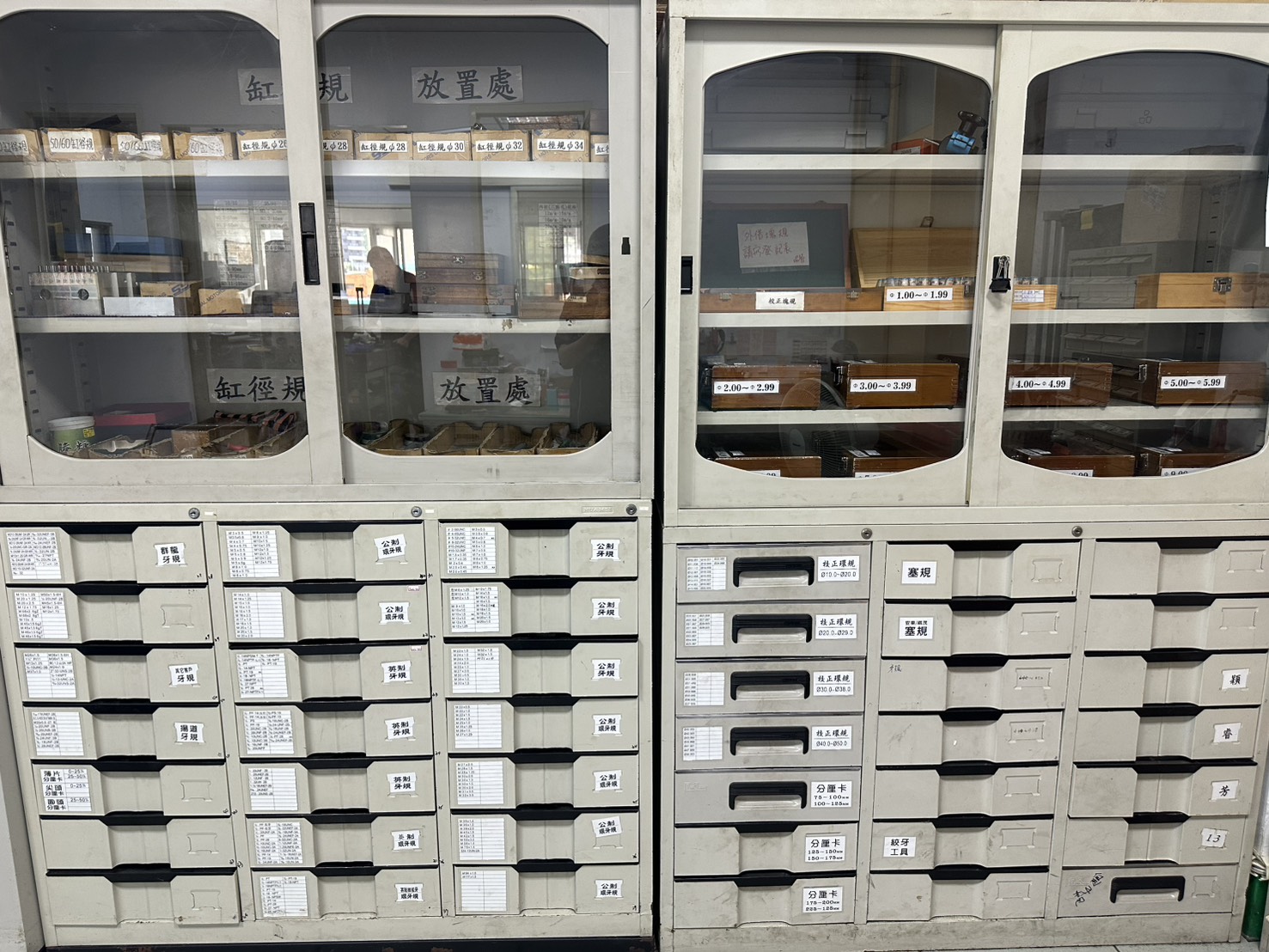
| Gauge type | Range held | Used for |
|---|---|---|
| Pin gauges | 0.5–10 mm | Hole diameter, pass/fail |
| Thread plug gauges, metric | Coarse and fine pitch | Internal threads, Go / No-Go |
| Thread ring gauges, metric | Coarse and fine pitch | External threads, Go / No-Go |
| Thread gauges, imperial | Common sizes held; specials added as required | UNC / UNF threads |
| Setting ring gauges | Ø10–50 mm | Zeroing bore gauges and micrometers |
| Outside micrometers | 75–225 mm | Outside diameters and lengths |
| Bore gauges | Ø18–35, Ø35–60, Ø50–150 mm | Bore diameter and roundness |
Building the gauge library
When a drawing calls for a thread we do not already hold a gauge for, we buy the gauge. This is a standing policy, not a case-by-case decision. Over the years it has built a store covering far more than the common coarse pitches: fine pitches such as M30 × 0.5 and M31 × 0.5 are checked with a dedicated Go / No-Go gauge instead of being inferred from other measurements.
The reason is repeat orders. Thread cutting depends on tooling that is set up again for every new run, and a setup verified only indirectly can drift from batch to batch without anything looking wrong. Checking every run against the same physical gauge keeps the thread on your tenth order identical to the thread on your first.
Every gauge we add stays in the store, so the next part with that thread is inspected against it from its first batch. Inspection capability builds up this way instead of starting over for each new job.
Calibration and Traceability
All measuring equipment is held under a documented instrument control system, with a management card for each instrument recording its identity, status and control category. Control falls into two categories.
Externally calibrated
The three coordinate measuring machines are calibrated by independent calibration laboratories, which issue a certificate for each machine. Those laboratories’ reference standards are in turn calibrated by an accredited laboratory, which maintains traceability.
Verified against a reference standard before use
Equipment supplied with a manufacturer’s calibration standard, namely the height gauges and the surface roughness testers, is checked against that standard before use, and the standard is replaced on a defined schedule. A fault that would put an instrument outside specification shows up at this check, before it reaches a part.
Measuring environment
Dimensional inspection is carried out in a metrology room held at 23 ±2 °C and 45–55 % RH, monitored continuously.
Calibration certificates for the equipment used on your parts can be supplied on request. Calibration status is reviewed as part of our Quality Control Process, and certificates can be issued alongside the Quality Inspection Report for your order.
Choosing the Right Measurement Method
The table below shows how we choose the right instrument for each feature, which keeps inspection both accurate and economical.
| Feature to verify | Method | Why |
|---|---|---|
| True position, profile, form, 3D geometry | CMM, contact | Only a probe can record points on surfaces that are not visible in an outline |
| Thin, soft, polished or easily deflected parts | Vision or image, non-contact | Probe contact force would deflect or mark the part |
| Many dimensions on one part | KEYENCE IM-8020 | One capture returns the whole set, so batch checking stays practical |
| Features on more than one face of a turned part | IM-8020 with rotary unit | Measured in one setup, without the error that re-fixturing introduces |
| Thread form, radii, chamfers | Profile projector | Silhouette comparison against an overlay is faster and clearer than probing |
| Heights, steps, hole pitch at the machine | Digital height gauge | Fast enough for in-process checks without leaving the shop floor |
| Threads and hole diameters, pass/fail | Thread and pin gauges | Attribute check: no reading to record, no operator interpretation |
| Hardness after heat treatment | Rockwell hardness tester | Material property, not dimensional |
| Surface finish, as-machined or plated | Surface roughness tester | Ra and Rz cannot be judged by eye or by touch |
Each project has its own inspection plan built from these methods. The plan is set during Quality Control Process, and the results are issued as the Quality Inspection Report for your order.
Frequently Asked Questions
Answers to the questions we are asked most often about how parts are measured and verified.
What tolerances can APPORO verify?
Inspection follows the 10:1 rule: measuring equipment is about ten times more accurate than the tolerance being checked. The KEYENCE IM-8020 measures to ±2 µm in high-precision mode, which supports verifying tolerances down to about ±0.02 mm. Tolerances tighter than ±0.01 mm are accepted and measured by comparison — the instrument is zeroed on a master at the nominal size, gauge blocks for outside diameters and setting rings for bores. Outside diameters have been supplied at ±0.005 mm.
Can I specify how a dimension must be inspected?
Yes — tell us at RFQ stage, on the drawing or in the RFQ itself. A specific instrument, a datum scheme, or your own inspection procedure can all be accommodated if we know before the job is quoted. Agreeing the method up front is what stops the same part reading in tolerance here and out of tolerance at your incoming inspection.
What coordinate measuring machines do you use?
Three DCC coordinate measuring machines are in service: a Sheffield Discovery 8 III, a Brown & Sharpe Gage 2000 and a Brown & Sharpe MicroXcel PFx 454. They are used where a drawing carries many dimensions, or features that are hard to reach any other way; simpler dimensions are checked on gauges, height gauges or the vision systems. Because the machines run programmed routines, every piece measured on a proven routine goes through the same sequence, with no operator variation.
Can thin, soft or polished parts be measured without damage?
Yes. The 2.5D vision measuring machines and the KEYENCE IM-8020 image dimension measurement system measure without touching the part, so no probe force can deflect or mark thin sections, soft materials or polished surfaces.
How are threads and hole diameters checked?
Threads and hole diameters are checked with Go / No-Go thread plug and ring gauges (metric coarse and fine pitch, and imperial UNC / UNF) and pin gauges, which give a pass or fail with no operator interpretation. Thread form, radii and chamfers are compared on the Baty R14 profile projector. When a drawing calls for a thread we do not already hold a gauge for, we buy the gauge.
Is your inspection equipment calibrated, and can I get certificates?
The three coordinate measuring machines are calibrated by independent calibration laboratories, which issue a certificate for each machine. Height gauges and surface roughness testers are checked against the manufacturer’s calibration standard before use. Certificates for the equipment used on your parts can be supplied on request.
What environment is dimensional inspection carried out in?
Dimensional inspection is carried out in a metrology room held at 23 ±2 °C and 45–55 % RH, monitored continuously.
What inspection records are available for my order?
Inspection records are produced for every order — a sample of three to five pieces, with every dimension on the drawing measured on each — and are kept on file. They are not sent automatically, because most customers do not want paperwork arriving with every delivery, but any record can be supplied on request. Ask when you place the order so the documentation can be prepared alongside it. The Quality Inspection Report page lists every document available and who issues each one.
{ "@context": "https://schema.org", "@type": "FAQPage", "mainEntity": [ {"@type": "Question", "name": "What tolerances can APPORO verify?", "acceptedAnswer": {"@type": "Answer", "text": "Inspection follows the 10:1 rule: measuring equipment is about ten times more accurate than the tolerance being checked. The KEYENCE IM-8020 measures to 2 micrometres in high-precision mode, which supports verifying tolerances down to about 0.02 mm. Tolerances tighter than 0.01 mm are accepted and measured by comparison: the instrument is zeroed on a master at the nominal size, gauge blocks for outside diameters and setting rings for bores. Outside diameters have been supplied at 0.005 mm."}}, {"@type": "Question", "name": "Can I specify how a dimension must be inspected?", "acceptedAnswer": {"@type": "Answer", "text": "Yes. Tell us at RFQ stage, on the drawing or in the RFQ itself. A specific instrument, a datum scheme, or your own inspection procedure can all be accommodated if we know before the job is quoted. Agreeing the method up front is what stops the same part reading in tolerance here and out of tolerance at your incoming inspection."}}, {"@type": "Question", "name": "What coordinate measuring machines do you use?", "acceptedAnswer": {"@type": "Answer", "text": "Three DCC coordinate measuring machines are in service: a Sheffield Discovery 8 III, a Brown and Sharpe Gage 2000 and a Brown and Sharpe MicroXcel PFx 454. They are used where a drawing carries many dimensions, or features that are hard to reach any other way; simpler dimensions are checked on gauges, height gauges or the vision systems. Because the machines run programmed routines, every piece measured on a proven routine goes through the same sequence, with no operator variation."}}, {"@type": "Question", "name": "Can thin, soft or polished parts be measured without damage?", "acceptedAnswer": {"@type": "Answer", "text": "Yes. The 2.5D vision measuring machines and the KEYENCE IM-8020 image dimension measurement system measure without touching the part, so no probe force can deflect or mark thin sections, soft materials or polished surfaces."}}, {"@type": "Question", "name": "How are threads and hole diameters checked?", "acceptedAnswer": {"@type": "Answer", "text": "Threads and hole diameters are checked with Go / No-Go thread plug and ring gauges (metric coarse and fine pitch, and imperial UNC / UNF) and pin gauges, which give a pass or fail with no operator interpretation. Thread form, radii and chamfers are compared on the Baty R14 profile projector. When a drawing calls for a thread we do not already hold a gauge for, we buy the gauge."}}, {"@type": "Question", "name": "Is your inspection equipment calibrated, and can I get certificates?", "acceptedAnswer": {"@type": "Answer", "text": "The three coordinate measuring machines are calibrated by independent calibration laboratories, which issue a certificate for each machine. Height gauges and surface roughness testers are checked against the manufacturer calibration standard before use. Certificates for the equipment used on your parts can be supplied on request."}}, {"@type": "Question", "name": "What environment is dimensional inspection carried out in?", "acceptedAnswer": {"@type": "Answer", "text": "Dimensional inspection is carried out in a metrology room held at 23 plus or minus 2 degrees C and 45 to 55 % RH, monitored continuously."}}, {"@type": "Question", "name": "What inspection records are available for my order?", "acceptedAnswer": {"@type": "Answer", "text": "Inspection records are produced for every order, a sample of three to five pieces, with every dimension on the drawing measured on each, and are kept on file. They are not sent automatically, because most customers do not want paperwork arriving with every delivery, but any record can be supplied on request. Ask when you place the order so the documentation can be prepared alongside it. The Quality Inspection Report page lists every document available and who issues each one."}} ] }